Whole House Water Filter Bypass Valve Purpose
A whole-house filter bypass valve lets you reroute water around the filter so service or pressure events don’t interrupt supply or damage cartridges and membranes. You’ll use it to isolate the filter, match bypass port flow to system GPM, and protect components during changeouts.
Correct orientation, verified pressure differentials, and clear indicators prevent unexpected flow or air ingress. Secure, labeled handles and proper port sizing ensure safe operation; continue for troubleshooting tips and setup checks.
Quick Overview
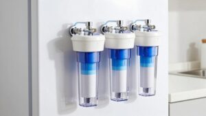
- Allows water to flow around the whole-house filter when servicing cartridges or replacing membranes.
- Prevents system shutdown by maintaining supply while isolating the filter housing.
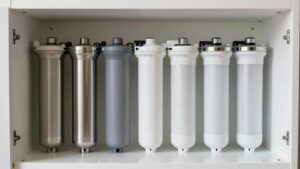
- Protects RO membranes and filters by matching bypass port size and pressure ratings during service.
- Enables pressure-differential diagnostics by isolating filter flow and comparing inlet/outlet pressures.
- Stabilizes flow during maintenance and prevents transient fluctuations when secured, locked, or tagged.
Bypass Valve Flow Rates
How much water will your bypass valve let through? You’ll match bypass valve sizing to pipe port size (3/4″ or 1″) and system specs to ensure GPM compatibility. Standard sediment bypasses cite 4 GPM for 3/4″ duty; larger 1″ ports support higher, unspecified rates that mirror main flow.
Select a bypass that avoids creating a restriction relative to peak household demand and pump capacity. Use metered or unrestricted (three-ball) bypasses where full-pipe flow is required. Verify pressure ratings and component fit for consistent performance and protection of RO membranes and filters during service.
| Variant | Port Size | Typical GPM |
|---|---|---|
| Sediment standard | 3/4″ | 4 |
| 1″ bypass | 1″ | System-dependent |
| Three-ball DIY | matches pipe | Full pipe flow |
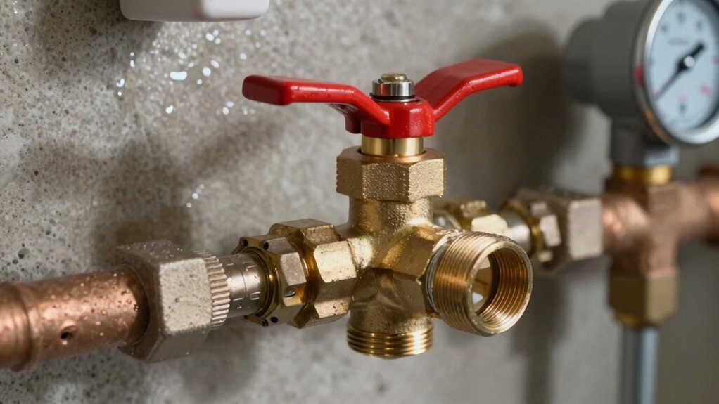
-Way Valve Orientation Guide
Which direction should the valve handle point for correct operation? You’ll orient handles based on flow paths and service needs; clear bypass orientation and valve alignment prevent misrouting. Follow these checks:
- Align handle parallel to the active pipe for normal flow; confirm inlet-to-outlet continuity.
- Turn handle perpendicular to isolate the filter; verify closed position with flow meter or visual indicator.
- Set intermediate angles only when the manufacturer specifies partial bypass; document valve alignment for future service.
- Lock or tag handles after adjustment to maintain bypass orientation during maintenance and to aid technicians.
You’ll perform final verification under low load. Watch pressure gauges for expected drops, and record positions in system logs to support maintenance and safe operation.
Pressure Differential Troubleshooting
When you troubleshoot pressure differentials, start by comparing inlet versus outlet pressures to locate the imbalance. Check valve position indicators and observe flow rate fluctuations to determine if the bypass or a closed stage is causing the issue.
Watch for upstream pressure loss or downstream restriction signs: air pockets, clogged cartridges, or closed valves can help pinpoint the fault.
Check Inlet vs Outlet
Want to quickly pinpoint whether a pressure-related issue lies upstream or downstream of your bypass valve? Perform an inlet check first: measure static and dynamic pressure immediately before the filter housing and document readings.
Then verify outlet alignment by measuring identical points immediately after the filter or bypass port. Compare differential values; a significant drop across the filter indicates clogging or internal restriction, while low inlet with normal outlet suggests upstream supply problems or regulator faults.
If inlet and outlet pressures match but system flow is low, inspect downstream valves, branching, or demand-side restrictions. Use calibrated gauges, isolate sections when possible, and repeat measurements under similar flow conditions to ensure valid comparisons.
Record results for trend analysis and maintenance planning.
Valve Position Indicators
How can valve position indicators help you diagnose pressure differentials across a bypass? You use clear valve labeling and consistent indicator visibility to compare inlet and outlet positions quickly. Visible indicators show which ports are open, so you can correlate observed pressure drops with specific valve states.
During troubleshooting, verify indicator alignment with handle stops and printed labels; misaligned indicators often explain unexpected differentials. Measure pressure upstream and downstream while toggling the bypass. Record changes against labeled valve positions to isolate restriction or leakage.
Ensure indicator visibility from normal access points and illuminate or mark indicators in low-light areas. Accurate valve labeling plus unambiguous indicators reduces diagnostic time and prevents incorrect valve maneuvers that could mask real pressure issues.
Flow Rate Fluctuations
Why is your flow rate fluctuating despite steady supply pressure? You should first consider transient changes in valve position or partial bypass activation altering flow dynamics. Small shifts create pressure differentials across filters, causing pulsatile or oscillatory output even when inlet pressure remains constant.
Inspect bypass seals, actuator linkages, and multiport valve detents for micro-movements that modulate throughput. Measure differential pressure across the cartridge during fluctuation episodes to correlate drops with flow instability. Verify that debris or partial channeling in the filter isn’t intermittently restricting flow, producing sudden stabilizing releases.
Corrective actions include securing the bypass mechanism, replacing worn seals, and cleaning filter elements to restore predictable flow paths. Restoring consistent internal hydraulics reestablishes flow stability and predictable household delivery.
Upstream Pressure Loss
Fluctuating flow often signals an upstream pressure loss that you’ll need to pinpoint quickly to restore steady delivery. Inspect the supply line, main shutoff, and incoming meter for obstructions or partial closures that reduce supply head.
Verify system gauges upstream and downstream of the filter; a consistent drop upstream with normal downstream indicates external supply issues rather than filter clogging. Use a temporary upstream bypass to isolate the filter assembly while you test pressure behavior.
Check for trapped air, corroded valves, or municipal pressure fluctuations; these can trigger unintended pressure relief device activation. Document transient events and correlate with pump cycles or utility notifications.
Correcting the upstream source prevents unnecessary reliance on the bypass and restores normal pressure regulation.
Downstream Restriction Signs
Where’s the flow being constricted downstream? Inspect fixtures, branch lines, and pressure-reducing valves for abrupt drops in pressure or intermittent surges. You’ll detect downstream restriction signs when pressure gauges show high upstream and low downstream readings across the filter housing while bypass valve flow rates remain elevated.
Check for clogged aerators, partially closed isolation valves, collapsed flexible tubing, or obstructed check valves. Measure differential pressure at multiple points to localize the restriction and confirm it’s not filter media compaction. If bypass valve flow rates increase when you close the filter path, the obstruction is downstream of the filter.
Document pressures before and after each component; isolate sections systematically and replace or clear the restricted element. Re-verify pressures after corrective action to confirm resolution.
Air Infiltration Symptoms
How can you tell air’s entered the system from the pressure readings? You’ll see rapid, irregular pressure spikes and drops across upstream and downstream gauges rather than steady differentials. Air pockets compress, producing transient high-pressure readings followed by abrupt falls when bubbles pass sensors.
Compare baseline differential with live values during flow; fluctuations greater than 10–15% indicate air contamination. Isolate sections using the filter bypass to confirm: open bypass and observe stabilization. If readings normalize, trapped air was likely in the filter housing or media.
Bleed vents and re-check for persistent oscillations that suggest upstream supply aeration. Document pressure patterns, time of occurrence, and operational state (pump on/off). Use this data to locate ingress points and prevent recurring air contamination.
Frequently Asked Questions
Yes, you can lock a bypass valve to prevent unauthorized use. You’ll install mechanical locks or tamper-proof covers, and integrate padlockable handles or lock-out/tag-out devices. For advanced control, you’ll add electronic actuators with access control and sensors tied to monitoring systems for audit trails.
Ensure locks meet local codes and allow emergency override. Regularly test locking mechanisms to maintain reliability and unauthorized use prevention.
Does a Bypass Affect Water Taste or Odor?
Yes, bypassing can change taste or odor. If you activate bypass maintenance or a permanent bypass, untreated water may carry minerals, chlorine, or organics that filters normally remove. Consequently, you’ll notice differences.
Frequent bypass use shortens filter lifespan when service resumes because trapped contaminants can shift and overload media. You should minimize bypass time, monitor water quality, and schedule prompt filter replacement to maintain consistent flavor and odor control.
Are Bypass Valves Compatible With Smart Home Systems?
Yes, you can integrate bypass valves with smart home systems. Many modern valves offer bypass compatibility via wired or wireless interfaces (Wi-Fi, Zigbee, Z-Wave) and digital actuators, enabling smart home integration for remote control, scheduled bypassing, and status monitoring.
You’ll want compatible controllers, proper sensor inputs (pressure, flow, TDS), and secure communication protocols. Installers should configure fail-safes and alerts to preserve safety and maintain reliable automated bypass operations.
How Often Should Bypass Valves Be Inspected or Tested?
You should inspect and test bypass valves every 3–6 months, and after any service or pressure event. For bypass maintenance, perform visual checks, cycle the valve, verify seals, and measure flow/pressure differentials.
Annually, do a full functional test and document results for water filtration calibration and trend analysis. Increase frequency if you notice pressure spikes, sensor alerts, or fluctuating TDS. Keep logs to support predictive maintenance and system reliability.
Can Bypass Operation Void My System Warranty?
Yes, improper bypass operation can void your warranty if it causes damage or violates installation rules. Check manufacturer terms for requirements on downstream compatibility and documented maintenance scheduling.
You should operate bypasses per specs; use compatible fittings; and log inspections or servicing. If you’re unsure, get written approval from the maker or a certified technician before changing bypass configurations to preserve warranty coverage and avoid liability for repair costs.
Conclusion
You’ll use the bypass valve to route flow around the filter when you need to service it, diagnose pressure differentials, or maintain supply during repairs. Orient the valve per the flow arrows so you don’t introduce crossflow, and verify inlet vs outlet pressures to spot upstream loss or downstream restriction.
Watch for indicator positions and sudden flow changes. Air infiltration and reduced downstream pressure signal sealing or piping faults. Operate the valve slowly to avoid water hammer.