Reverse Osmosis System Features Checklist
You’ll verify filter flow rates and restrictor sizing to hit target GPD.
You will match membrane GPD to household demand and account for temp and pump curves.
You’ll confirm membrane rejection for salts, hardness, organics, and microbes.
Note test conditions and apply conservative fouling margins.
You’ll set pressure switch cut-in and cut-out, as well as adjustable differential to prevent short-cycling.
Lock out on low feed, and set high-pressure trips.
You’ll also specify sensor accuracy, hysteresis, and calibration intervals; continue for full procedure.
Quick Overview
- Match membrane capacity and restrictor/flow rates to household demand and desired recovery: use GPD and ML/min targets.
- Specify membrane rejection rates with test conditions and conservative allowances for aging and fouling.
- Define explicit pressure switch cut-in/cut-out values and adjustable differential to prevent short-cycling.
- Require pressure sensor accuracy (±1–2% FS), hysteresis/deadband, and periodic calibration against a certified manometer.
- Verify restrictor selection, multi-stage pressure drops, temperature effects, and pump requirements during commissioning.
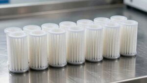
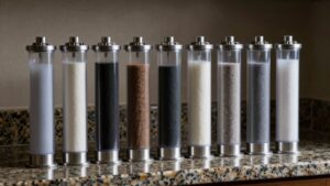
Filter Flow Rates Chart
The Filter Flow Rates Chart presents recommended flow restrictor settings, typical flow rates, and expected daily production for common RO membrane sizes. This allows you to size restrictors and anticipate system output accurately. Use the listed GPD ratings (8–1,200) and corresponding ML/min or GPM guidance to match membrane capacity with feed conditions and application requirements.
You will use restrictor values (150–500 ML/min or specified GPM ranges) to set recovery and production targets; this helps in balancing flux, recovery, and production-to-drain ratio. Consider filter performance impacts and installation considerations, including multi-stage pressure drops, temperature effects, and pump requirements. Match membrane GPD to household demand (25–800+ GPD) and verify restrictor selection during commissioning to ensure expected daily production and efficient wastewater management.
| Parameter | Guidance |
|---|---|
| Restrictor | Select per GPD table |
| Verification | Test flow and tank fill rate |
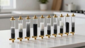
Membrane Rejection Rates Guide
How well does a membrane remove specific contaminants, and how should you interpret those removal figures when specifying an RO system? You evaluate membrane efficiency by comparing manufacturer rejection percentages for target solutes under standardized test conditions. Translate those percentages into expected product quality given your feed composition and operating pressures.
- Review rejection rates for salts, hardness ions, organics, and microbes.
- Confirm test conditions (temperature, pressure, salt type) match your system or apply correction factors.
- Combine rejection data with flow measurement of permeate to compute mass removal and required membrane size (GPD).
- Use conservative margins for aging membranes and fouling to ensure long-term compliance.
Document assumptions, test sources, and margins when you specify the membrane.
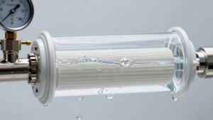
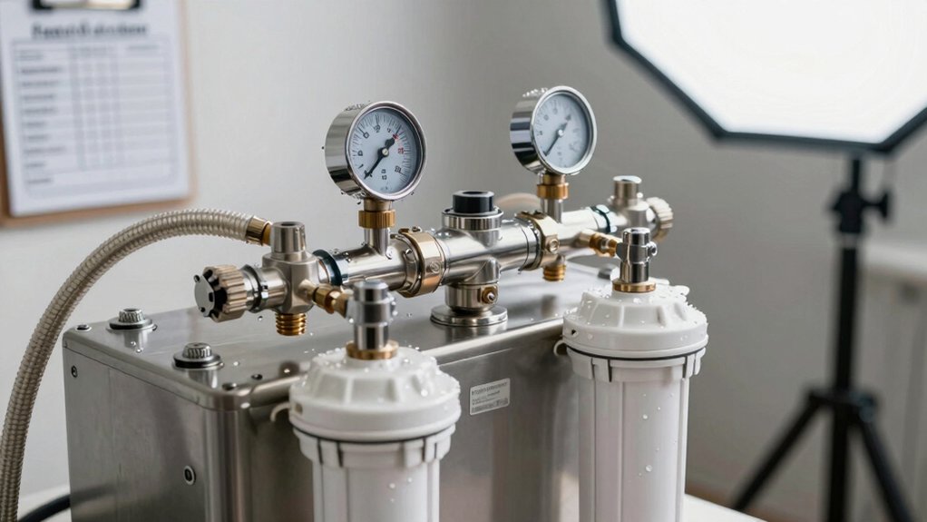
Pressure Switch Setpoints
You’ll set pressure switch cut-in and cut-out points to match your pump and membrane operating range, typically specifying both values explicitly. Adjust the differential to control pump cycling while observing high-pressure trip limits and low-pressure lockout thresholds to protect the membrane and pump.
Verify pressure sensor accuracy and calibration to ensure the switch setpoints actuate reliably under real feed and permeate conditions.
Typical Cut-In/Cut-Out
Wondering what pressure switch setpoints you should expect on an RO booster or tank-fill system? You’ll typically see a typical cut in around 30–40 psi and a cut out near 50–60 psi; though manufacturer specs vary. The pressure switch monitors system pressure and signals the pump to start at the cut in and stop at the cut out to maintain tank charging and protect the membrane.
When you select or inspect setpoints, verify they match pump curve and tank precharge so cycling is minimized. Confirm deadband and repeatability, and ensure wiring and mounting prevent false trips. Document the pressure switch setpoints and test under normal feed conditions to confirm reliable operation.
Adjustable Pressure Differential
An adjustable pressure differential lets you set precise cut-in and cut-out setpoints on a booster or tank-fill pressure switch, so the pump only runs when necessary; this minimizes cycling and protects the membrane. You’ll use adjustable pressure settings to match pump capacity, tank volume, and membrane feed requirements.
Specify differential operation range that prevents short-cycling while ensuring adequate feed pressure under peak draw. Set cut-in low enough to allow full tank discharge but above osmotic back pressure; set cut-out to stop pump when tank refill meets demand margin.
Verify switch hysteresis, mechanical calibration, and electrical connections during commissioning. Document setpoints, test under variable flow, and adjust incrementally to optimize pump life, water recovery, and membrane performance without exceeding system tolerances.
High-Pressure Trip Limits
Why set a high-pressure trip limit precisely? You protect membranes, fittings, and the pump by using defined high pressure trip limits tied to operational thresholds. You’ll calculate setpoints from maximum membrane feed pressure, pump curve, and allowable vessel rating.
Configure your pressure switch setpoints to trip before component yield strength or membrane compaction limits are approached; typically, a few psi below manufacturer maximums. Implement hysteresis to prevent nuisance cycling and document sensor calibration intervals. When you commission, increment pressure while monitoring permeate flow, concentrate ratio, and seal integrity. Record the trip event and adjust if transient spikes occur.
Maintain a locked configuration with authorized-change logging to ensure repeatable and safe operation of the RO system.
Low-Pressure Lockout
Because low feed pressure can quickly damage pumps and reduce membrane recovery, you should set a low-pressure lockout that prevents pump start or trips the system when feed pressure falls below a safe threshold.
You’ll define the lockout setpoint based on pump NPSH, membrane minimum feed pressure, and expected operating margins. Configure a differential between restart and trip to avoid rapid cycling; a typical hysteresis of 3–5 psi is appropriate but validate against manufacturer data.
Use a pressure switch rated for the system’s hydraulic range and mount it on the feed manifold upstream of prefilters to capture true feed conditions. Implement alarm contacts and interlock with the control PLC so the system locks out on sustained low pressure and records the event for maintenance.
Pressure Sensor Accuracy
How accurately does your pressure sensor need to report feed pressure to set reliable pressure-switch setpoints? You should specify tolerance bands based on system pressure and membrane requirements; typically ±1–2% full-scale for control-grade performance.
Define setpoint hysteresis and deadband to prevent rapid cycling of pumps and valves. Verify pressure accuracy through routine sensor calibration against a certified manometer at multiple points across the operating range. Log deviations and adjust setpoints if drift exceeds allowable limits tied to membrane osmotic back pressure and automatic shut-off thresholds.
Use sensors with documented long-term stability and temperature compensation. Implement a maintenance schedule for recalibration and replacement to sustain operational safety, efficiency, and consistent recovery rates.
Frequently Asked Questions
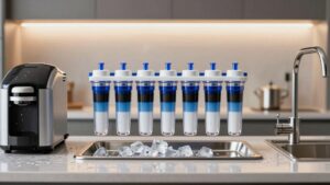
How Often Should Pre-Filters Be Replaced in Residential Systems?
You should replace pre-filters every 6–12 months depending on feed water quality and usage. For a reliable pre-filter replacement and maintenance schedule, inspect sediment and carbon cartridges every 3 months. Change sooner if you see pressure drop, discoloration, or taste/odor return.
In high-sediment or heavy-use homes, replace at 3–6 months. In low-use, low-contaminant conditions, you can extend to 9–12 months while monitoring performance.
Can RO Systems Remove Chloramines Without Specialized Filters?
No, you won’t remove chloramines effectively with a standard RO membrane alone. Chloramines removal requires specialized filters. You should use catalytic activated carbon or specific chloramine-targeted media upstream of the membrane to protect TFC elements.
These specialized filters chemically reduce chloramines; they prevent membrane degradation and maintain rejection rates. Install and replace them per manufacturer specs, and verify performance with periodic residual disinfectant testing to ensure sustained chloramines removal.
What Tank Size Is Ideal for a Family of Four?
You should choose a 3.2–4 gallon tank for a family of four. Assess tank size against family needs: demand peaks, faucet flow, and system GPD. A 50 GPD membrane matched to a 3.2–4 gallon bladder tank yields usable volume and reasonable recovery time.
Install a post-filter and ensure automatic shut-off and proper pressure to optimize delivery. Monitor daily use and upgrade to a larger tank if peak shortages occur.
Is a Booster Pump Necessary for Low Incoming Pressure?
Yes, you’ll likely need a booster pump if you have low pressure. Residential systems require sufficient feed pressure to overcome osmotic and permeate back pressures. A booster pump raises flow, improves recovery, and reduces wastewater.
You should also monitor pre filters replacement intervals since clogged prefilters lower feed pressure and can mimic pump issues. Select a pump sized for your membrane GPD and install per manufacturer specs for reliable performance.
How Should Concentrate Wastewater Be Safely Disposed Of?
You should route concentrate wastewater to a proper drain or sewer per local codes, using an air gap or approved saddle valve and corrosion‑resistant piping to prevent leaks.
For how to dispose concentrate wastewater safely, test for contaminants and neutralize or pretreat if required. Document discharge volumes and constituents for regulatory compliance considerations. Obtain permits when needed, and keep maintenance records to demonstrate adherence to limits and best management practices.
Conclusion
You’ve got the essential parameters to specify, monitor, and troubleshoot an RO system effectively. Use the filter flow rates chart and membrane rejection guide to size components. Set pressure switch setpoints and typical cut-in/cut-out values to protect membranes. Adjust pressure differential for fouling control and program high-pressure trip limits and low-pressure lockout for safety.
Verify pressure sensor accuracy regularly and document every setpoint change to maintain reliable, repeatable operation.