
Reverse Osmosis Faucet Installation Overview
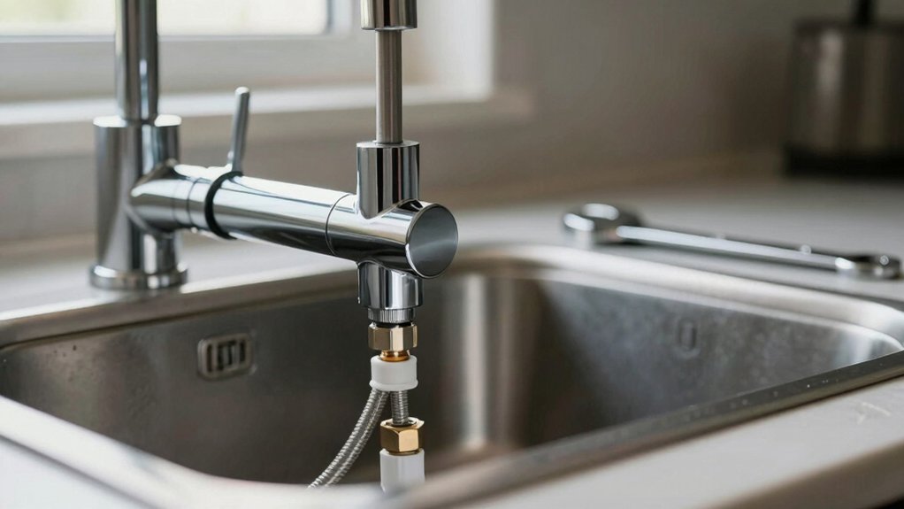
You’ll drill a 1/2″–1 3/8″ hole (max 1-1/4″ countertop) for the RO faucet. Use 1/4″ tubing with 2.75″ stud length, and confirm hole diameter before cutting.
Start compression fittings finger-tight; then torque 1/4″ fittings to 20–25 in·lb and 3/8″ to 25–30 in·lb, seating ferrules and checking alignment. Fit check valves with arrows matching flow from membrane to tank to prevent backflow.
Tighten, pressurize, inspect for leaks, and verify valve seating; more specifics follow.
Quick Overview
- Confirm faucet hole size and max deck thickness before drilling. Typical stud length is 2.75″ and max surface is 1-1/4″.
- Start compression fittings finger-tight; then torque 1/4″ tubing to 20–25 in·lb and 3/8″ to 25–30 in·lb in one step.
- Orient check valves so molded arrows match intended flow from membrane outlet toward storage tank.
- Ensure ferrules seat properly. Cut tubing square, secure inlet/outlet tubing, and verify tubing cannot be pulled free.
- Pressurize system; check for leaks and correct flow direction. Mark or photograph valve orientation for future service.
/8″ Compression Dimensions
How much clearance do you need for the compression shank? You’ll need a shank clearance that accommodates the 2.75″ stud length and up to 1-1/4″ mounting surface thickness. Plan for access beneath the countertop to secure the brass nut and lock washer.
The compression shank accepts mounting hole sizes from a snug 1/2″ up to 1 3/8″. So, confirm hole diameter before drilling. Use the table to match dimensions to function and ensure 1/4″ tubing compatibility.
| Feature | Value |
|---|---|
| Stud Length | 2.75″ |
| Mounting Hole Range | 1/2″ – 1 3/8″ |
| Max Surface Thickness | 1-1/4″ |
| Tube Compatibility | 1/4″ tubing |
/8″ Compression Torque Specs
Why tighten the compression nut to a specific torque? You need repeatable compression calibration so seals seat without deforming ferrules or tubing. Use torque consistency to prevent leaks and allow future maintenance.
- Use a calibrated torque wrench: apply 20–25 in·lb for 1/4″ tubing, 25–30 in·lb for 3/8″. Start finger-tight; then torque in one step.
- Verify seating: after initial torque, pressurize the system and recheck torque values. If leak-free, mark nut position for torque consistency during service.
- Avoid over-torquing: excess force will crush ferrules and cause hard-to-detect failures. Under-torquing allows micro-leaks. Record settings as part of the installation log and adjust slightly only when replacing components, following manufacturer specs.
Filter Check Valve Orientation
Check valves prevent backflow in the RO feed and reject lines. So, you’ll want to confirm each valve’s purpose and flow direction before installation.
Orient the valve so its arrow matches the intended flow and tighten fittings to the manufacturer’s torque to avoid leaks or damage. Incorrect orientation or loose fittings can allow contamination or pressure issues. Therefore, double-check markings and hand-plus-quarter-turn tightness where specified.
Check Valve Purpose
Where should the filter check valve face? You should orient the check valve so it permits flow away from the membrane and toward the storage tank/faucet, ensuring check valve safety and effective backflow prevention.
Install it inline immediately after the membrane or permeate outlet per manufacturer specs, keeping tubing runs short and unobstructed. Verify the valve seating is clean and aligned; a misaligned valve can stick open and defeat backflow prevention.
Use quick-connect fittings properly seated and test under pressure for leaks and reverse flow. If service is required, depressurize the system first. Document valve orientation for future maintenance and replace any valve showing wear or hesitation to close, maintaining consistent one-way operation and protecting the membrane from tank feed pressure.
Flow Direction Markings
Having oriented the check valve to allow flow from the membrane toward the tank, next confirm the valve’s flow direction marking before finalizing installation. You’ll inspect the molded arrow or stamped triangle on the valve body; it must point in the direction of flow direction from RO membrane outlet to storage tank.
If markings are obscured, rotate the valve assembly until the arrow aligns with tubing path and verify against system layout. Secure tubing on the inlet and outlet sides, then pull lightly to confirm retention. Document the check valve orientation in your installation notes and photograph the marking for future service. Correct flow direction prevents backflow, protects the membrane, and ensures proper tank filling without additional troubleshooting.
Proper Valve Orientation
Why must the filter check valve face the flow from the membrane toward the tank? You orient the check valve so its arrow points downstream; this ensures unidirectional flow from membrane to storage. Proper valve orientation prevents reverse pressurization of the membrane housing and ensures the tank only fills when the post-filter path is open.
Install the valve immediately after the membrane outlet using secure fittings and correct tube sizes. Confirm seating and torque to manufacturer spec. You’ll minimize pressure loss and maintain system efficiency by avoiding turbulence and leaks at the junction. While this addresses valve orientation, remember that correct placement contributes to the overall backflow prevention strategy without substituting for dedicated backflow devices covered later.
Preventing Backflow Risks
How should you orient the filter check valve to prevent backflow? You’ll install the check valve with the arrow pointing in the direction of purified water flow, from the membrane outlet toward the storage tank and faucet. That orientation ensures one-way operation and provides positive flow prevention when tank pressure fluctuates.
Mount the valve vertically or horizontally as manufacturer allows; keep tubing runs short and free of sharp bends that could impair sealing. Verify the valve seat is clean and the housing is fully seated to avoid leakage that defeats flow prevention.
After installation, pressurize the system and observe for reverse flow at fittings. Any backflow indicates incorrect orientation, debris in the seat, or a faulty check valve that needs replacement.
Installation Tightness Tips
Now that the check valve orientation is set, focus on tightening to guarantee a leak-free, one-way seal without over-stressing plastic fittings. You’ll achieve correct installation tightness by hand-starting threaded plastic parts. Then, apply measured wrench turns: typically a quarter to half turn until firm.
For compression fittings, seat the ferrule squarely. Advance the nut finger-tight, then complete with a wrench using the manufacturer’s specified increments. Avoid excessive torque; this can crack housings or deform ferrules and compromise the check valve.
Inspect compression details: ferrule alignment, clean tubing ends, and correct insertion depth. Once tightened, visually confirm that ferrules compress evenly and tubing cannot be pulled free. Keep fittings accessible for final adjustment after initial system pressurization.
Testing Valve Function
Before pressurizing the system, verify the filter check valve orientation and operation to prevent backflow and assure unidirectional flow. Inspect the check valve arrow or marking; confirm it points toward the faucet/pure-water line.
Use testing valve function ideas: manually actuate the feed valve, then isolate the membrane feed and observe whether downstream pressure holds. If pressure bleeds back, the check valve may be reversed, damaged, or obstructed.
With the system pressurized briefly, open the RO faucet and listen for steady flow without sputtering. This indicates correct unidirectional operation. Close the faucet and monitor for pressure decay at the tank and downstream lines.
Replace or rotate the check valve if you detect leakage or incorrect flow direction. Re-test after any correction to ensure reliable operation.
Frequently Asked Questions
Can I Reuse My Existing Sink Sprayer Hole for the RO Faucet?
Yes, you can reuse your existing sink sprayer hole for the RO faucet if it’s positioned for drinking or cooking access and the mounting surface meets thickness and flatness limits.
You’ll remove the sprayer, cap its supply, and install the RO shank through the hole; securing from below. This keeps plumbing tidy and supports recycling water practices. It also integrates with home automation-friendly systems that monitor flow and filter status.
What Drill Bit Should I Use for a Stainless Steel Sink?
Use a step bit for stainless steel sinks; it gives clean, controlled enlargements without grabbing. Wear eye protection, clamp a wood backing, and use masking tape to protect the finish.
Drill slowly with cutting fluid and steady pressure to avoid work-hardening. You’ll finish faster than fiddling with brittle bits after a long hiking trip or a board games night. The step bit’s staged steps prevent chipping and give precise 2″ hole sizing.
How Thick Can the Countertop Be for Mounting the Faucet?
You can mount the faucet on a thick countertop up to 1-1/4 inches; anything thicker compromises mounting feasibility. If your countertop exceeds that, you’ll need an adapter, a thinner mounting surface, or a custom shank extension.
Verify the mounting surface is flat and at least 2 inches wide. Use proper tools and confirm clearance beneath the sink to ensure secure fastening and proper orientation without interfering with plumbing or cabinet components.
Do Air-Gap Faucets Require Additional Drain Connections?
Yes, do air gap faucets require additional drain connections. You’ll route an air-gap housing with two drain lines: one from the RO unit to the air gap and one from the air gap down to the sink drain (or disposer).
You must secure fittings, avoid kinks, and use the correct adapter size. Ensure the drain path is above the trap to prevent siphoning. Test for leaks after tightening all connections.
How Do I Cap the Sprayer Connection if Unused?
Cap the sprayer by removing the sprayer hose and installing a threaded cap or plug rated for plumbing on the unused connection.
If you reuse the hole and retain the faucet, fit the cap onto the sprayer’s tailpiece under the sink. Use Teflon tape on the threads, and tighten with an adjustable wrench.
Verify no leaks; trim excess hose, and secure tubing to prevent kinks or strain on the connection.
Conclusion
You’ve now got the key details to install an RO faucet correctly: size and torque for 3/8″ compression fittings, how the check valve must face flow direction, and why it blocks backflow into the membrane.
Tighten fittings to specified torque; don’t overtighten and orient the check valve per flow markings. After installation, pressurize the system and verify the valve closes under reverse pressure.
If the valve fails, replace it to protect the membrane and water quality.
You may also like: Faucet Diverter Valves — a related guide worth bookmarking.
You may also like: To Identify Faucet Thread Size — a related guide worth bookmarking.