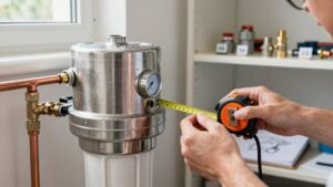
Under Sink Water Filter Space Requirements
You should reserve clear vertical, front, and side space so you can remove a 10–14″ cartridge straight down or out. Keep about 2″ extra for hands and a wrench, 1″ side clearance, and 3–4″ front clearance for seals. Leave 1½” below housings for service and place leak sensors low near valves, seams, and connections within 6–12″ of fittings and 18–24″ apart.
Route power away from drips and test wireless range to ensure alerts: more specifics follow.
Quick Overview
- Measure vertical clearance to fit the filter body plus cartridge length, and leave at least 2″ extra for hands and a wrench.
- Maintain a minimum 1½” gap below housings for maintenance access and filter removal.
- Leave 1″ side clearance and 3–4″ front clearance to avoid rubbing and allow cartridge extraction.
- Place leak sensors low near valves, tank seams, and beneath housings; space no more than 18–24″ along drip paths.
- Route power along cabinet walls away from drips; use GFCI protection, and verify wireless sensor range (20–50 ft) before final install.
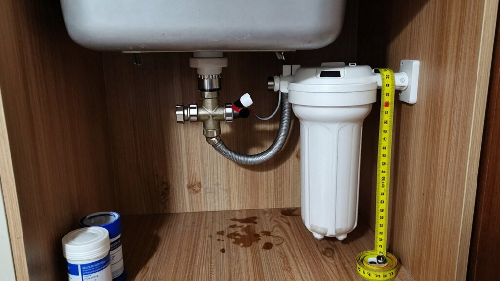
Under-Sink Clearance Diagram
Where will you grab the cartridge when it’s time to replace it? You’ll plan an under sink clearance diagram showing filter height, cabinet floor and a minimum 1-1/2 inch gap below the housing for maintenance access.
Mark leak detection and sensor placement near the lowest point; keep power wiring routed away from potential drips. Note wireless signal and coverage radius if you use battery or Wi‑Fi sensors so alerts reach your hub.
| Item | Requirement | Note |
|---|---|---|
| Vertical gap | 1-1/2 in min | Cartridge removal |
| Sensor location | Lowest point | Leak detection |
| Wiring | Routed separately | Avoid water contact |
| Wireless | Coverage radius | Verify hub reach |
Measure cabinet depth and width against housing dimensions before final installation.
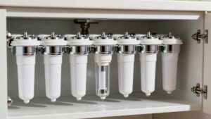
.5″ Filter Cartridge Clearance
How will you grab and replace the cartridge without fighting the cabinet? Plan for cartridge access by following simple under sink clearance rules: Leave enough front and vertical room so you can pull a 10–14″ cartridge straight down or out. Account for the system body (Hydroviv 14″ H, PWP 18″) and replaceable element sizes when measuring.
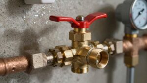
Measure vertical drop: Allow cartridge length plus 2″ for hands and wrench. Keep 1″ side clearance to avoid rubbing and permit slight rotation. Reserve 3–4″ front clearance to extract housings and change seals. Position tubing and shutoff so they don’t block removal; label valves for quick shutoff.
These practical steps reduce fumbles and speed routine cartridge swaps.
Leak Detection Sensor Placement
Place sensors low and near likely leak sources: valves, tank seams, cartridge connections. This positioning allows them to catch drips before they spread. Check each sensor’s coverage radius and plan spacing. Then confirm power and wiring or wireless range to ensure reliable alerts.
You’ll also map expected leak points and verify signal strength through cabinet walls or around metal tanks before final mounting.
Sensor Placement Height
Why should you set leak sensors at specific heights under the sink? You’ll use sensor placement to catch leaks early without false triggers. Position sensors at the lowest points where water pools: cabinet floors, around drain traps, and near storage tank bases. While keeping a small height clearance above fittings, avoid splashes setting them off.
Mount sensors on short risers if you need to detect slow weeps under raised components or beside tall tanks. For systems with metal or plastic tanks, place sensors at the tank base and at a secondary mid-height for rapid detection of larger failures. Ensure wiring and battery access remain reachable.
Test placement by pouring a cup of water to confirm prompt alerts. Adjust height clearance to balance sensitivity and durability.
Leak Source Mapping
Where should you position sensors to pinpoint the origin of an under-sink leak? Place one sensor directly beneath the filter housing or tank to detect primary leak source signals immediately. Add sensors at connection points: inlet valve, outlet tubing, quick-connect fittings, and shutoff valve.
Mount a thin sensor along the floor edge under the cabinet to catch slow drips that travel. If you have multiple components (tank, RO unit, cartridge stack), stagger sensors vertically to distinguish which component is leaking.
Keep sensor placement predictable and documented so you can trace alerts to exact components. Test each sensor after installation with a controlled moisture exposure. Good sensor placement reduces false positives and shortens the time to isolate the leak source for fast repairs.
Coverage Radius Requirements
Because leaks can spread quickly under cabinetry, you’ll want sensors positioned so each component’s drip radius is covered. Aim for sensors within 6–12 inches of individual fittings, tanks, and filter housings. Place sensors no more than 18–24 inches apart along likely drip paths.
Place sensors at low points and near joints, valves, and cartridge housings where seals and O-rings fail most often. Account for coverage radius when laying out components so a single sensor can monitor multiple nearby parts. Keep sensors clear of moving parts and allow recommended installation clearance for filters and tanks to avoid false triggers during maintenance.
Test placement with a small water source to confirm detection. Then, label locations for quick troubleshooting if an alarm sounds.
Power And Wiring
Now that your sensors are positioned to catch drips, plan how you’ll power them and run wiring without creating trip hazards or interference with under-sink components. Route power wiring along cabinet walls; keep cables tight to surfaces and away from filter housings, tanks, and valves.
Use adhesive clips or cable channels to secure leads. Keep wires at least a few inches from water lines and moving parts. If you need an outlet, mount a GFCI-protected receptacle outside the immediate wet zone or use a GFCI adapter. Prioritize electrical safety at every step.
Avoid running cords across the cabinet floor or behind tanks where they can be pinched. Label connections and test sensors after installation to confirm reliable power and placement.
Wireless Signal Considerations
How close should you place wireless leak sensors to guarantee reliable alerts? Place sensors within the manufacturer’s stated signal range, typically 20–50 feet indoors, and test connectivity before final mounting.
Mount sensors on the cabinet floor near likely leak points: under fittings, near tanks, and along tubing runs. Keep them clear of large metal objects and dense plumbing that cause wireless interference. If the cabinet sits under thick counters or behind metal braces, move sensors closer to the cabinet opening or add a repeater.
For multi-stage systems with storage tanks or RO units, place at low points where water pools. Always run a quick alert test from the intended sensor spot. If signal fails, adjust location or add a bridge to ensure consistent notifications.
Maintenance And Access
When you place leak sensors, prioritize easy access for testing and battery changes while keeping them at likely failure points: under fittings, near the storage tank, and along tubing runs. This way, you can quickly inspect, reset, or replace devices without dismantling the system. Mount sensors on flat surfaces and route wires so they don’t snag on cartridges or tank valves.
Include clear labels and a small service diagram inside the cabinet door to speed technician tasks. Tie sensor checks into your maintenance planning and set recurring access scheduling for monthly visual inspections and semiannual functional tests. Position sensors where condensate or slow drips collect, not only at high-flow outlets. That way, you reduce downtime, avoid surprises, and simplify routine cartridge or tank servicing.
Frequently Asked Questions
Can I Install the Filter in a Corner Cabinet With Angled Walls?
Yes, you can, but you’ll need to plan. You’ll fit most under-sink filters into a corner cabinet with angled walls if you measure carefully and avoid the garbage disposal area.
Position the tank and filter where depth and height clear angled panels. Keep 1″ clearance for vibration-sensitive units, and route tubing around obstacles. You’ll probably mount components on flat cabinet faces or a bracket to maintain service access.
Will the System Fit Inside a Cabinet With a Garbage Disposal Present?
Yes, you can, but measure first. You’ll need enough disposal clearance and cabinet depth to fit the chosen tank and filters alongside the disposal.
Check heights: many tanks (PWP 15–20” H, Midea ~34 cm) and housings (Hydroviv 14” H, Waterdrop ~18”) may conflict with disposal plumbing. Leave 1”–2” for tubing and access. If space is tight, consider smaller units, remote tanks, or relocating the disposal inlet.
Can I Use Softener-Treated Water With the Filter System?
Yes, you can use soft water with the filter system, but check compatibility. Soft water reduces scale, easing membrane and cartridge life. However, excessive sodium from ion exchange can affect taste and certain filters.
Maintain proper hardness balance by monitoring replacement schedules and rinsing cartridges if recommended. Follow manufacturer specs for pressure and temperature. Confirm the system tolerates softened feed water to avoid voiding warranties or reducing performance.
How Loud Will the System Be During Normal Operation?
You’ll hear minimal noise during normal operation; most under-sink filters are quiet. Expect low hums from flow or occasional clicks when tanks fill. Noise levels are typically negligible.
If you install a Waterdrop or similar, leave a 1-inch gap to avoid vibration concerns. Tighten fittings to stop rattles. Reverse osmosis pumps are louder; choose an insulated cabinet or quieter tank if sound matters to you.
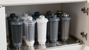
Do Filters Need Space for Monthly Cartridge Rotation?
Yes, you’ll need enough room to swap cartridges easily. Allow clearance above and around the housing so you can pull cartridges straight down or out. Leave side access for twisting or disconnecting fittings.
Measure the cartridge dimensions (and tank if present); add a few inches for hands and tools. Plan layout so monthly replacements are quick and mess-free.
Conclusion
You’ve now got the essentials to install and service an under-sink filter without surprises. Allow at least 0.5″ clearance for cartridges. Mount leak sensors near likely leak points and at a low height. Map coverage so sensors overlap key areas.
Route power and wiring to avoid moisture; prefer low-voltage or GFCI-protected circuits. Check wireless range before final placement. Keep access clear for maintenance and quick cartridge changes. Simple, safe, reliable.
You may also like: Under Sink Filter Shopping Checklist — a related guide worth bookmarking.
You may also like: Sink Water Filter Installation Basics — a related guide worth bookmarking.